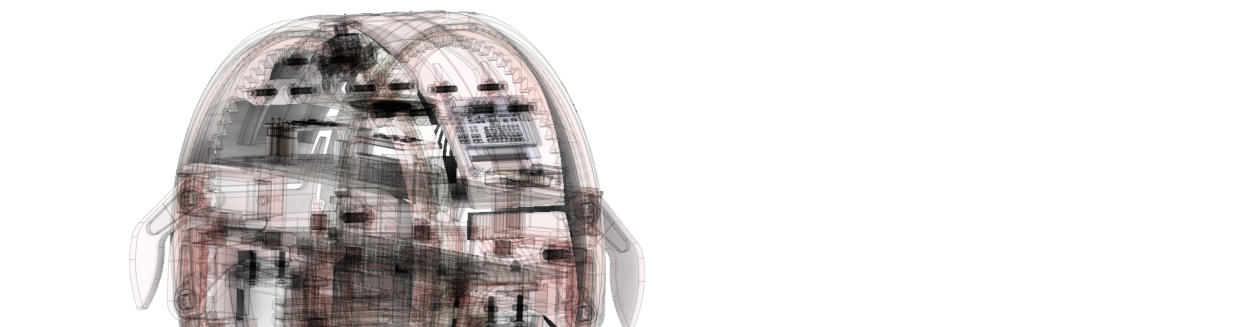


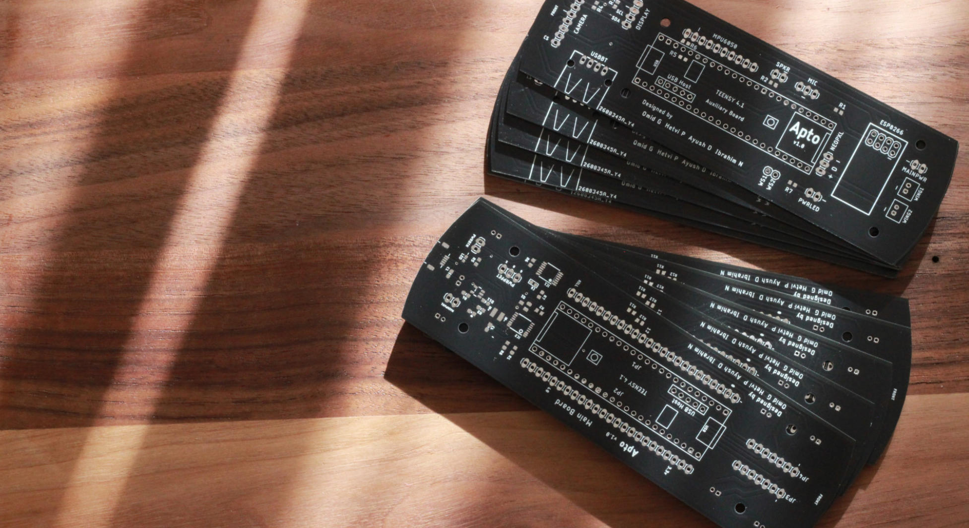
Built using a custom stacked PCB design, created to fit the unique shape
and structure of Apto.
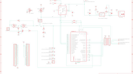
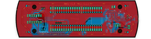
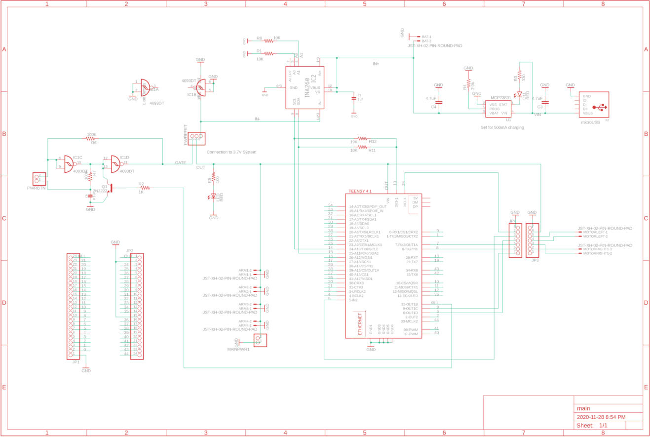
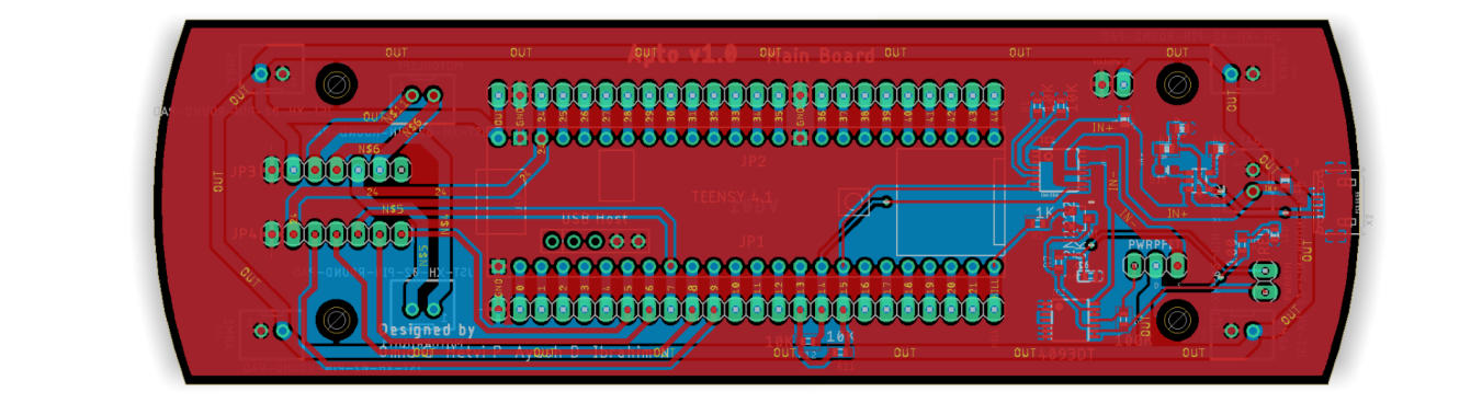
Designed to accommodate the electronics needed to bring Apto to life, the main schematic contains a series of ICs and breakout pins necessary for
controlling the individual functionalities of the robot. Included onboard is the Teensy 4.1 ARM Cortex-M7 microcontroller, Lithium Ion charging circuit, INA260 current
and voltage monitor, push button power IC, DRV8835 Motor Controller board, and breakout JST connectors for powering each servo.


Find complete documentation, source code, and CAD files.
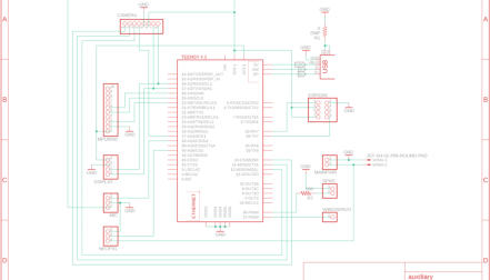
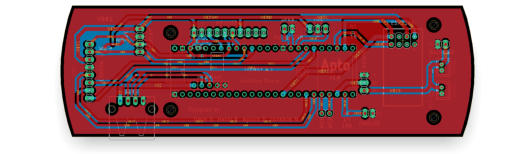
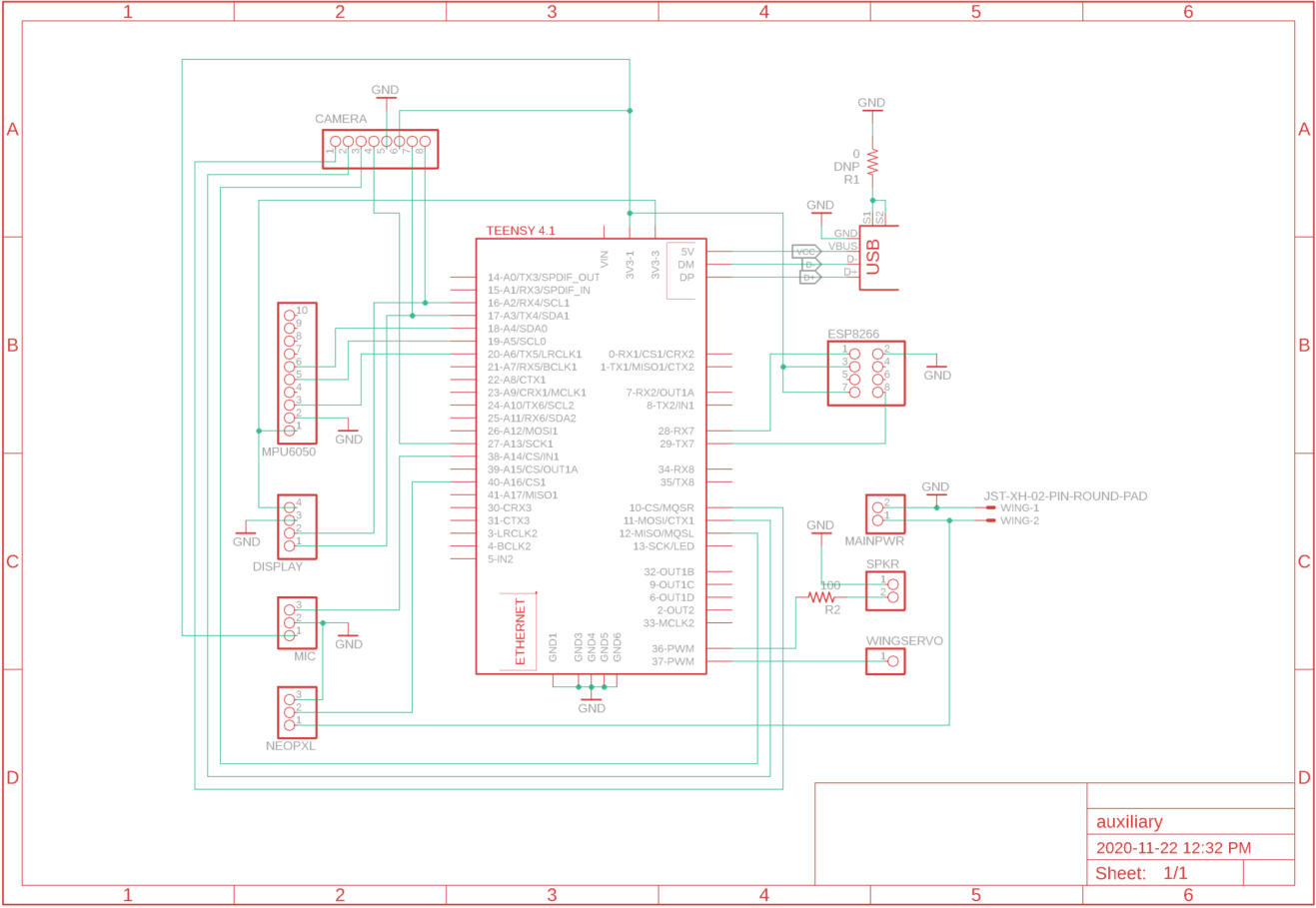
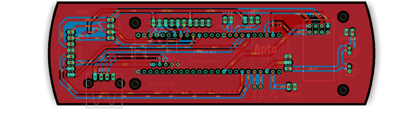
Designed to accommodate the peripheral electronics connected to Apto. Included onboard are breakout pins for a ESP8266 WiFi module, OV2640 2MP Camera,
MPU6050 Accelerometer + Gyroscope, 0.96” Display, Microphone, Speaker, Neopixels and USB for the CSR 4.0 Bluetooth adapter.


Download print ready CAD files over on Thingiverse.


Download the EagleCAD PCB FILES on Github.
The main board was designed for a 2 layer PCB with 1.6mm thickness. It contains both through holes for soldering a Teensy 4.1 and Pololu Dual Motor Driver
as well pads for the remaining surface mounted components. Four 3mm drill holes are used to mount the PCB to the main chassis. A micro USB port is used to recharge the battery.
The auxiliary board contains a series of different sized header pins to connect various external modules. It includes a female USB port to add support for
a Bluetooth dongle.