


The remote controlled robot, called Apto, was built to operate in two modes of transportation, walking and driving. It was built for the purpose of
exploring and interacting with various environments. Its intelligent part consists of an onboard microcontroller featuring an ARM Cortex-M7 processor.
Apto’s wide array of sensors include an Arducam 2MP Camera, Current & Voltage Sensor, Accelerometer + Gyroscope, and microphone. The two modes
of operation consist of four legs made up of servos for walking, and 2 DC motors connected to wheels for driving.
Apto can be broken down into separate subsystems including Power, Guidance Navigation and Controls (GNC), Electromechanics, Network and User
Interface.
Hardware was selected in a manner that allowed Apto to have a wide variety of capabilities while still being able to keep its power consumption low.
The Teensy 4.1 development board was chosen as it contains a powerful yet small ARM Cortex M7 processor. A 6000mAh 3.6V Lithium Polymer battery
was used as the power source of the robot. 9g servos were chosen for the arms, while DC motors will be used for driving mode. A dual motor H-bridge
controller will be used for direction and speed control. An accelerometer based around the MPU-9250 IC with an integrated gyroscope will be used for
keeping track of trajectories. An OV2640 Mini 2MP camera module will be used for the capturing images of its environment.
Other components of the robot include a PS3 controller to control the movement of the robot via Bluetooth, a 0.5W 8 Ohm speaker, microphone, OLED
Display, and Neopixel LEDs for lighting. With respect to power, there is a micro-USB charging circuit, current and voltage sensor, LED status indicator
and a power distribution board.
SUBSYSTEM
COMPONENT
QUANTITY
POWER
ELECTROMECHANICAL
GUIDANCE, NAVIGATIONS
AND CONTROL
NETWORK
USER INTERFACE
Lithium-Ion Polymer (LiPo) Battery (3.7V 6000mAh Stacked)
1
Cherry MX Switch
1
FQP27P06 - P-Channel MOSFET (-60V -27A)
1
Micro JST 2.0 Ph 2-Pin Connector Plug Male & Female
10
Longruner MG90S Metal Geared Micro Servo Motor 9G
12
⅛” Steel Ball Bearings
200
1V-6V DC Hobby Motor EK1894C
2
Teensy 4.1 ARM Cortex M7 Microcontroller
1
Arducam Mini Module Camera Shield with OV2640 2 Megapixels Lens
1
ESP8266 ESP-01 Serial WiFi Module
1
Pololu Dual Motor Driver DRV8835 Carrier (2-11V 1.2A)
1
MPU-6050 Accelerometer/Gyroscope IMU
1
Bluetooth 4.0 USB Dongle Adapter (CSR 4.0)
1
0.96” I2C Serial OLED Display Module (128x64)
1
0.5W 8 Ohm Speaker
Dual Shock Wireless PS3 Controller
5mm LED
Electret Microphone
WS2812 Neopixel Individually Addressable LED
1
1
1
1
10
POWER
Pin
Devices
Vin (3.7V) BAT
ARM1,2,3,4
MOTOR
NEOPIXEL
3.3v-1
WIFI MODULE
DISPLAY
CAMERA
3.3v-3 (250
mA)
MIC
ACCELEROMETER
MOTOR
CONTROLLER
Logic
Pin
Teensy
Output
Device
Device Input
0
PWM
1
PWM
2
PWM
ARM1-1 DATA
DATA
3
PWM
ARM1-2 DATA
DATA
4
PWM
ARM1-3 DATA
DATA
5
GPIO
MOTOR CONTROLLER
MODE
6
GPIO
MOTOR CONTROLLER
APHASE
7
PWM
MOTOR CONTROLLER
AENBL
8
GPIO
MOTOR CONTROLLER
BPHASE
9
PWM
MOTOR CONTROLLER
BENBL
10
PWM
ARM2-1 DATA
DATA
11
PWM
ARM2-2 DATA
DATA
12
PWM
ARM2-3 DATA
DATA
13
PWM
ARM4-1 DATA
14
PWM
ARM4-2 DATA
DATA
15
PWM
ARM4-3 DATA
DATA
16
SCL1
DISPLAY
SCL
17
SDA1
DISPLAY
SDA
18
SDA0
ACCELEROMETER
SDA
19
SCL0
ACCELEROMETER
SCL
20
GPIO
ACCELEROMETER
INT
21
A7
22
PWM
DATA
23
PWM
DATA
24
SCL2
CURRENT SENSOR
SCL
25
SDA2
CURRENT SENSOR
SDA
26
MOSI1
CAMERA
MOSI
27
SCK1
CAMERA
SCK
28
PWM
WING DATA
29
PWM
Extra PWM Pin
30
GPIO
NEOPIXEL
DATA
31
GPIO
POWER LED
POS
32
GPIO
PUSH POWER BTN
KILL
33
PWM
ARM3-1 DATA
DATA
34
RX8
WIFI MODULE
TX
35
TX8
WIFI MODULE
RX
36
PWM
ARM3-2 DATA
DATA
37
PWM
ARM3-3 DATA
DATA
38
CS1
CAMERA
CS
39
MISO1
CAMERA
MISO
40
A16
MIC
OUT
41
A17
SPEAKER
POS
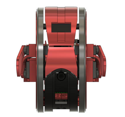
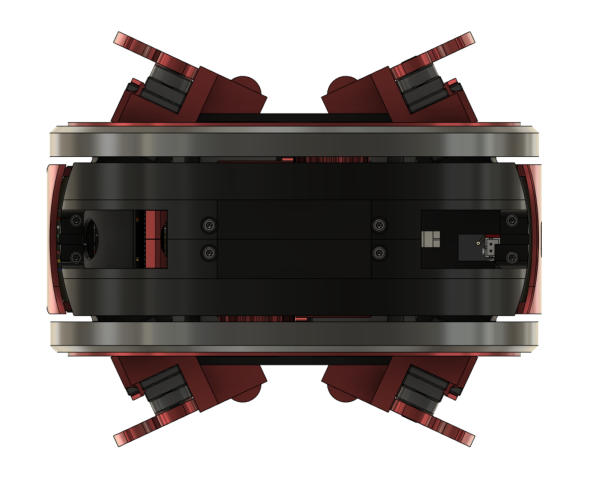
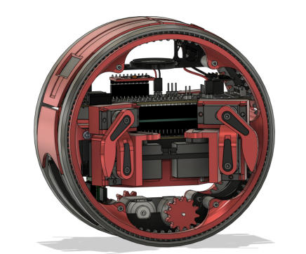
Apto’s structural design does not only influence the way it interacts with its environment but, it also determines how complex the software and
hardware have to be. One of Apto’s main features is its ability to act as a two-wheeled tank driven robot or as a 4-legged quadruped robot at any given
moment. It accomplishes this using an innovative mechanical design which allows for the legs to be tucked inside the wheels while driving. In the
event Apto wishes to move as a quadruped (potentially to move over an obstacle), the legs can extend out of the robot and begin walking.
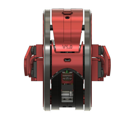
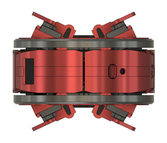
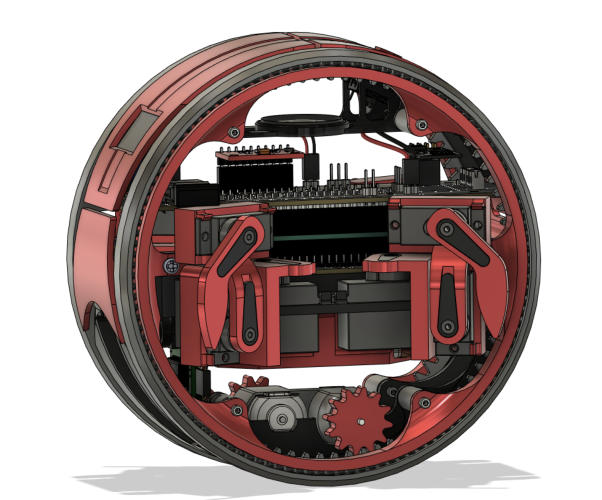


The arms and wheels have clearance to move due to the use of a custom designed inverted turntable gear system. Essentially the wheel of the robots
acts as a bearing with its inner circumference acting as a gear which is driven by a small DC motor located at the base of the robot. This is mirrored
across both sides of the robot and allows Apto to drive using a dual motor driver circuit.
Front View
Back View
Top View
Bottom View
Side View


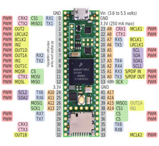
The electrical design of the robot began with building a schematic around the hardware selected. This involved reading through the datasheets for
each of the components to determine the pinout for every IC and breakout board used in the project. The next step was to map each of these pins to
an input or output pin on our microcontroller. Again, to ensure the correct operation of each component, the Teensy datasheet was followed. Certain
pins needed to be prioritized due to the large number of sensors, specifically to reserve PWM pins for sending data to each of the servos. To
accommodate all the onboard electronics, we needed to design a custom PCB that could fit our needs. We split electrical components onto two
different PCBs labelled as the main and auxiliary boards.


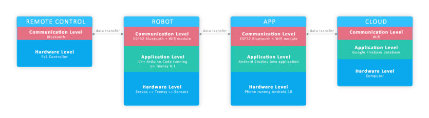
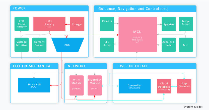
The software & communication hierarchy present for Apto exists as many layers working with each other to exchange data. We specifically chose to
build our software hierarchy this way in order to standardize communication across an app, cloud database, and robot itself. The figure below
showcases the communication between the robot, controller, app, and cloud. Note that both Bluetooth and WIFI protocols are used in this
communication system. This was chosen by design as we saw Apto’s best use of Bluetooth communication was at close range where the user can
visually see the response of the robot to the input. Then, the ESP8266 WIFI module is used to communicate and log telemetry data onto a cloud
database. The use of Wi-Fi in this scenario is an excellent representation of how IOT is currently utilized throughout society. In our case Apto logs its
data remotely to an android app to poll it and display its contents through a GUI.
DEVICE
PACKAGE
QUANTITY
MC14093B-TSSOP14
1
4UCONN_20329
1
TSSOP16
1
PN87520
SOT23-5
SOT23-BEC
LED-0603
1
CHIP-LED0603
1
Resistor
3
Resistor
1
Resistor
2
Resistor
1
Resistor
8
Resistor
2
Capacitor
1
1
2
LABEL
IC1
IC2
DESCRIPTION
4093DT Quad 2-input NAND schmitt trigger for power button
INA260 Voltage Current Sensor IC
X2
Female Micro USB Connector
Female USB-A Connector
USBBT
MCP73831 Miniature single cell fully integrated Li-Po charging IC
U1
MMBT2222ALT1 NPN Transistor
Q1
1
1
1
Red charge status LED
Blue power LED
D11
LED
0603
0603
3 Pin SMD
5 Pin SMD
16 Pin SMD
14 Pin SMD
0603
0603
0603
0603
0603
0603
R5 Main, R2,R7 Aux
1K Ohm
R3 Main
R2 Main, R1 Aux
330 Ohm
100 Ohm
10K Ohm
100K Ohm
2K Ohm
R4 Main
R1,R8,R11,R12 Main
R3,R4,R5,R6 Aux
R6,R7 Main
Capacitor
0.1uF
1uF
4.7uF
Capacitor
C6 Main
C1 Main
C3,C4 Main
0603
0603
0603


The process of making a quadruped robot walk involves the development of a walking gait. A gait by definition is a person’s (or an object’s) manner of
walking. Creating an effective walking gait is imperative for Apto’s mobility as it will determine how well it can traverse rough or uneven terrains. In
order to develop a robot’s walking gait, we typically require an algorithm that can calculate movements of all joints based only on the desired endpoint.
This concept is known as inverse kinematics which in our scenario is more desirable than traditional forward kinematics. This is because from a
developer’s point of view, we only want to send commands informing our program to move Apto’s foot from x1, y1 to x2, y2. Programmatically, this can
be accomplished by first declaring structures which represent the body and legs of the robot. To learn more about the software behind Apto and how
exactly the walking gait is implemented, check out the complete code over on our Github.
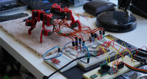
Each arm was programmed and tested using the rig pictured above. This held the individual arms in the correct position to mimic the main chassis.


The remote controlled robot, called Apto, was built to operate in two modes
of transportation, walking and driving. It was built for the purpose of
exploring and interacting with various environments. Its intelligent part
consists of an onboard microcontroller featuring an ARM Cortex-M7
processor. Apto’s wide array of sensors include an Arducam 2MP Camera,
Current & Voltage Sensor, Accelerometer + Gyroscope, and microphone. The
two modes of operation consist of four legs made up of servos for walking,
and 2 DC motors connected to wheels for driving.
Apto can be broken down into separate subsystems including Power,
Guidance Navigation and Controls (GNC), Electromechanics, Network and
User Interface.
Hardware was selected in a manner that allowed Apto to have a wide
variety of capabilities while still being able to keep its power consumption
low. The Teensy 4.1 development board was chosen as it contains a
powerful yet small ARM Cortex M7 processor. A 6000mAh 3.6V Lithium
Polymer battery was used as the power source of the robot. 9g servos were
chosen for the arms, while DC motors will be used for driving mode. A dual
motor H-bridge controller will be used for direction and speed control. An
accelerometer based around the MPU-9250 IC with an integrated
gyroscope will be used for keeping track of trajectories. An OV2640 Mini
2MP camera module will be used for the capturing images of its
environment.
Other components of the robot include a PS3 controller to control the
movement of the robot via Bluetooth, a 0.5W 8 Ohm speaker, microphone,
OLED Display, and Neopixel LEDs for lighting. With respect to power, there
is a micro-USB charging circuit, current and voltage sensor, LED status
indicator and a power distribution board.
SUBSYSTEM
COMPONENT
QUANTITY
POWER
ELECTROMECHANICAL
GUIDANCE, NAVIGATIONS
AND CONTROL
NETWORK
USER INTERFACE
Lithium-Ion Polymer (LiPo) Battery (3.7V 6000mAh Stacked)
1
Cherry MX Switch
1
FQP27P06 - P-Channel MOSFET (-60V -27A)
1
Micro JST 2.0 Ph 2-Pin Connector Plug Male & Female
10
Longruner MG90S Metal Geared Micro Servo Motor 9G
12
⅛” Steel Ball Bearings
200
1V-6V DC Hobby Motor EK1894C
2
Teensy 4.1 ARM Cortex M7 Microcontroller
1
Arducam Mini Module Camera Shield with OV2640 2 Megapixels Lens
1
ESP8266 ESP-01 Serial WiFi Module
1
Pololu Dual Motor Driver DRV8835 Carrier (2-11V 1.2A)
1
MPU-6050 Accelerometer/Gyroscope IMU
1
Bluetooth 4.0 USB Dongle Adapter (CSR 4.0)
1
0.96” I2C Serial OLED Display Module (128x64)
1
0.5W 8 Ohm Speaker
Dual Shock Wireless PS3 Controller
5mm LED
Electret Microphone
WS2812 Neopixel Individually Addressable LED
1
1
1
1
10
POWER
Pin
Devices
Vin (3.7V) BAT
ARM1,2,3,4
MOTOR
NEOPIXEL
3.3v-1
WIFI MODULE
DISPLAY
CAMERA
3.3v-3 (250
mA)
MIC
ACCELEROMETER
MOTOR
CONTROLLER
Logic
Pin
Teensy
Output
Device
Device Input
0
PWM
1
PWM
2
PWM
ARM1-1 DATA
DATA
3
PWM
ARM1-2 DATA
DATA
4
PWM
ARM1-3 DATA
DATA
5
GPIO
MOTOR CONTROLLER
MODE
6
GPIO
MOTOR CONTROLLER
APHASE
7
PWM
MOTOR CONTROLLER
AENBL
8
GPIO
MOTOR CONTROLLER
BPHASE
9
PWM
MOTOR CONTROLLER
BENBL
10
PWM
ARM2-1 DATA
DATA
11
PWM
ARM2-2 DATA
DATA
12
PWM
ARM2-3 DATA
DATA
13
PWM
ARM4-1 DATA
14
PWM
ARM4-2 DATA
DATA
15
PWM
ARM4-3 DATA
DATA
16
SCL1
DISPLAY
SCL
17
SDA1
DISPLAY
SDA
18
SDA0
ACCELEROMETER
SDA
19
SCL0
ACCELEROMETER
SCL
20
GPIO
ACCELEROMETER
INT
21
A7
22
PWM
DATA
23
PWM
DATA
24
SCL2
CURRENT SENSOR
SCL
25
SDA2
CURRENT SENSOR
SDA
26
MOSI1
CAMERA
MOSI
27
SCK1
CAMERA
SCK
28
PWM
WING DATA
29
PWM
Extra PWM Pin
30
GPIO
NEOPIXEL
DATA
31
GPIO
POWER LED
POS
32
GPIO
PUSH POWER BTN
KILL
33
PWM
ARM3-1 DATA
DATA
34
RX8
WIFI MODULE
TX
35
TX8
WIFI MODULE
RX
36
PWM
ARM3-2 DATA
DATA
37
PWM
ARM3-3 DATA
DATA
38
CS1
CAMERA
CS
39
MISO1
CAMERA
MISO
40
A16
MIC
OUT
41
A17
SPEAKER
POS
Apto’s structural design does not only influence the way it interacts with its
environment but, it also determines how complex the software and
hardware has to be. One of Apto’s main features is its ability to act as a two-
wheeled tank driven robot or as a 4-legged quadruped robot at any given
moment. It accomplishes this using an innovative mechanical design
which allows for the legs to be tucked inside the wheels while driving. In
the event Apto wishes to move as a quadruped (potentially to move over an
obstacle), the legs can extend out of the robot and begin walking.
The legs and wheels have clearance to move due to the use of a custom
designed inverted turntable gear system. Essentially the wheel of the
robots acts as a bearing with its inner circumference acting as a gear which
is driven by a small DC motor located at the base of the robot. This is
mirrored across both sides of the robot and allows Apto to drive using a
dual motor driver circuit.
Front View


Side View


The electrical design of the robot began with building a schematic around the
hardware selected. This involved reading through the datasheets for each of
the components to determine the pinout for every IC and breakout board
used in the project. The next step was to map each of these pins to an input or
output pin on our microcontroller. Again, to ensure the correct operation of
each component, the Teensy datasheet was followed. Certain pins needed to
be prioritized due to the large number of sensors, specifically to reserve PWM
pins for sending data to each of the servos. To accommodate all the onboard
electronics, we needed to design a custom PCB that could fit our needs. We
split electrical components onto two
different PCBs labelled as the main and auxiliary boards.
The software & communication hierarchy present for Apto exists as many
layers working with each other to exchange data. We specifically chose to
build our software hierarchy this way in order to standardize communication
across an app, cloud database, and robot itself. The figure below showcases
the communication between the robot, controller, app, and cloud. Note that
both Bluetooth and WIFI protocols are used in this communication system.
This was chosen by design as we saw Apto’s best use of Bluetooth
communication was at close range where the user can visually see the
response of the robot to the input. Then, the ESP8266 WIFI module is used to
communicate and log telemetry data onto a cloud database. The use of WiFi
in this scenario is an excellent representation of how IOT is currently utilized
throughout society. In our case Apto logs its data remotely to an android app
to poll it and display its contents through a GUI.
The process of making a quadruped robot walk involves the development of
a walking gait. A gait by definition is a person’s (or an object’s) manner of
walking. Creating an effective walking gait is imperative for Apto’s mobility
as it will determine how well it can traverse rough or uneven terrains. In
order to develop a robot’s walking gait, we typically require an algorithm that
can calculate movements of all joints based only on the desired endpoint.
This concept is known as inverse kinematics which in our scenario is more
desirable than traditional forward kinematics. This is because from a
developer’s point of view, we only want to send commands informing our
program to move Apto’s foot from x1, y1 to x2, y2. Programmatically, this can
be accomplished by first declaring structures which represent the body and
legs of the robot. To learn more about the software behind Apto and how
exactly the walking gait is implemented, check out the complete code over
on our Github.


Apto Remote Control
Quadruped Robot
By Omid G, Hetvi P, Ayush D
Ibrahim N


last updated on Jan. 17, 2021.